In photo #1, you can see the "set" furnace unit. Set meaning the unit is fixed to the spot chosen for the final location of the furnace. Before we move through the system, notice photo #2. This photo shows you how the furnace is divided into 2 cabinets...the burner cabinet (top) and the blower cabinet (bottom). This is reversed in a down-flow system where the duct work is located below the unit. A horizontal unit will be set up the same as an up-flow most often and just laid onto its' side. The modifications to a horizontal unit have more to do with drainage than cabinet arrangement. (Note: A high efficiency furnace creates condensation in the flu pipes. These pipes drain back toward the furnace and from there, discharged to a drain in the floor or a pump of some sort.) Now back to photo #1.
This set unit is raised slightly off the ground by cork/rubber pads (Vibration Pads) that prevent noise that would be created by metal vibrating on concrete. Often bricks will be added as well to raise the unit further off the ground; preventing water from entering the unit should mild flooding occur in the basement.
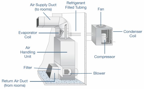
Located directly on top of the furnace is the air conditioning systems evaporator coil. This is what makes this a split system...the coil is "split" from the condensing unit that is located outside the home in most cases. Refrigerant is pumped into the evaporator coil where the pressure is changed thus changing the boiling point of the refrigerant. This process, simplified, makes the coil cooler than the air passing over it. Like a cold glass of water on a warm day, the coil pulls the humidity from the air and cools it at the same time. Again, there's more science behind it than that but you get the idea. The coil must be installed level or just slightly toward the coil drain outlet so that the collected condensation can be drained off properly, just as in the high efficiency furnace. (Photo #2 is of a factory cased coil. Coils can be purchased uncased but ultimately must be cased in some fashion to contain the air to the system.)
On top of the coil is the plenum. This is the first piece of duct work in the system that all others in the supply ducting will originate from. This could be a plenum with one opening big enough to carry the entire amount of needed supply air when located at the far end of a home or it could be a "T" plenum. A "T" plenum is used when the furnace is more centrally located in the home (suggested) and the openings on either side are sized to carry the amount of air required on each side of the home. There is also a box plenum. This type of plenum is used in a "spider" system where all heat runs are fed directly from the box and there is no "trunk-line". There are a few other various types but they are not as common and we'll stop at these 3 examples.
Lastly, the piece of metal attached to the side of the unit you see in photo #1 is called the return air "boot". This piece is where the air will finally return to the blower cabinet. We'll come back to this as we follow the airflow through the system.
Share this Post
latest post
-
 Universal Condenser Fan Motor June 30, 2023
 -
 Root Cellar Temperature June 30, 2023
 -
 Residential Heating And Cooling Systems June 30, 2023
 -
 Damp Basement Floor Solution June 30, 2023
 -
 Furnace Return Air Ducts June 16, 2023
 -
 Return air Grille May 22, 2023
 -
 Damp Proofing membrane Manufacturers May 17, 2023
 -
 Crawl space ventilation formula May 12, 2023
 -
 Wood cold air return covers May 7, 2023